
Introduction
Microservices solutions are more and more popular. Docker, Kubernetes are more and more popular, even the hardest opponents start to give up. Unfortunately we – Software Developers – usually do not like to focus on network protocols. That ignorance can sometimes be a blessing, but sometimes can hit us hard in the most painful time. In this article I want to focus on the Transmission Control Protocol protocol limits of source and destination ports size and why it can be painful for us.
Transmission Control Protocol port analysis
The RFC9293 https://www.ietf.org/rfc/rfc9293.txt describes transmission protocol. Paragraph 3.1 Header Format defines following protocol details.
A TCP header, followed by any user data in the segment,
is formatted as follows, using the style from [66]:

  0                   1                   2                   3
   0 1 2 3 4 5 6 7 8 9 0 1 2 3 4 5 6 7 8 9 0 1 2 3 4 5 6 7 8 9 0 1
  +-+-+-+-+-+-+-+-+-+-+-+-+-+-+-+-+-+-+-+-+-+-+-+-+-+-+-+-+-+-+-+-+
  |          Source Port          |       Destination Port        |
  +-+-+-+-+-+-+-+-+-+-+-+-+-+-+-+-+-+-+-+-+-+-+-+-+-+-+-+-+-+-+-+-+
  |                        Sequence Number                        |
  +-+-+-+-+-+-+-+-+-+-+-+-+-+-+-+-+-+-+-+-+-+-+-+-+-+-+-+-+-+-+-+-+
  |                    Acknowledgment Number                      |
  +-+-+-+-+-+-+-+-+-+-+-+-+-+-+-+-+-+-+-+-+-+-+-+-+-+-+-+-+-+-+-+-+
  |  Data |       |C|E|U|A|P|R|S|F|                               |
  | Offset| Rsrvd |W|C|R|C|S|S|Y|I|            Window             |
  |       |       |R|E|G|K|H|T|N|N|                               |
  +-+-+-+-+-+-+-+-+-+-+-+-+-+-+-+-+-+-+-+-+-+-+-+-+-+-+-+-+-+-+-+-+
  |           Checksum            |         Urgent Pointer        |
  +-+-+-+-+-+-+-+-+-+-+-+-+-+-+-+-+-+-+-+-+-+-+-+-+-+-+-+-+-+-+-+-+
  |                           [Options]                           |
  +-+-+-+-+-+-+-+-+-+-+-+-+-+-+-+-+-+-+-+-+-+-+-+-+-+-+-+-+-+-+-+-+
  |                                                               :
  :                             Data                              :
  :                                                               |
  +-+-+-+-+-+-+-+-+-+-+-+-+-+-+-+-+-+-+-+-+-+-+-+-+-+-+-+-+-+-+-+-+

         Note that one tick mark represents one bit position.

                    Figure 1: TCP Header Format

   where:

   Source Port:  16 bits
     The source port number.

   Destination Port:  16 bits
     The destination port number.
To set up a connection we need to define two ports: Source Port and Destination Port. Destination port is already defined and limited to a single value. I guess you are aware that each HTTPS connection usually uses port 443. Source port is usually chosen randomly – values below 1024 are usually reserved. Good practice is that Source Port gets values above 32000. If you call the command netstat in the console you can see both source and destination ports’ numbers.
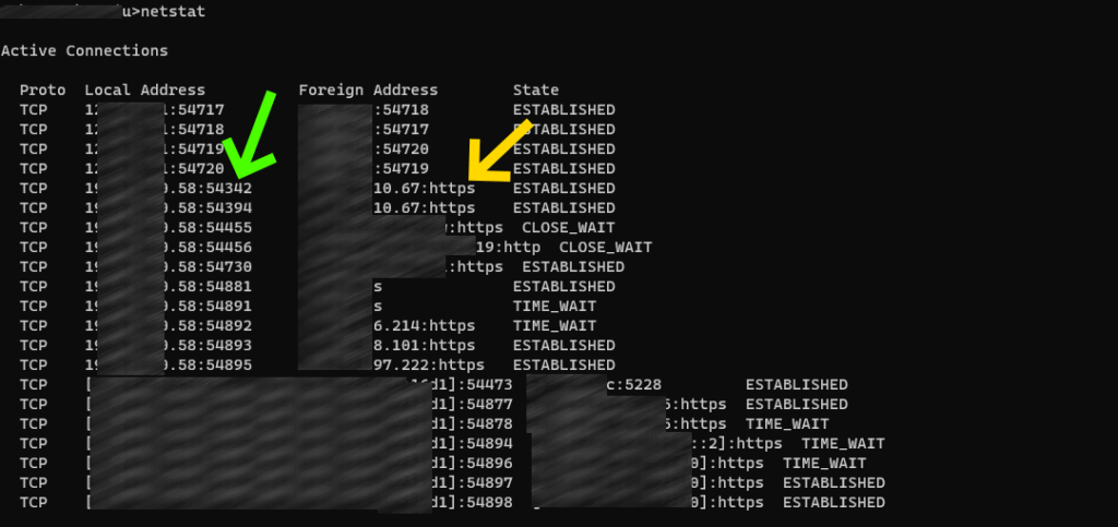
Green arrow shows different source ports, yellow arrow shows destination ports.
Where I see a problem
I am going to focus on both values: Source Port size 16 bits and Destination Port size 16 bits. You can see that we have theoretically 64K source ports and 64K destination ports. I already pointed out that the destination port is limited usually to a single value. So the theoretical limit is 64K independent connections, but reality is that the Source Port will not get more than 32K independent values.
32K connections is a lot and for a single machine is usually true. When we assume that a broken connection usually is removed from client and server after 60 seconds it gives us over 500 new connections per second if we assume a really unstable network. Now imagine that your Kubernetes cluster hosts multiple services and each service connects to an external single resource. You can be blinded by the fact that each service instance uses a different IP address, so the problem does not exist. Unfortunately you have forgotten the fact that the internal structure of the cluster does not leak outside. Outgoing traffic must pass some kind of Network Address Translation routing service. So the whole cluster is visible outside as a single client with a single IP address. If you get a few hundreds of services on a single cluster connecting e.g. to a single Azure Service Bus, Azure Storage etc. you can easily notice that your services start to starve and cannot initiate a new connection. That is why planning the architecture of your services in advance is so important.
Possible solutions
There is no single solution – silver bullet – for this problem.
- Developers should try to limit outgoing connections creation to not exhaust connections pool available on cluster.
- Architects should analyze communication patterns and work on the best solution.
- Shared resources can be placed inside the cluster so we can remove NAT from the communication chain.
- The cluster can be assigned to multiple IP addresses, so the available source port numbers limit can be balanced between different IP addresses.
- We can create a Virtual Private Network between the cluster and the shared resource, to remove NAT for the equation.
The problem is not trivial to solve. We must analyze all options and make the best choice for us. Anyway the first step is to be aware of such issues. That is why I wrote this article to help you protect your design at the start not after production release, when it can be too late to react.